LT1-360-8.c File Reference
LT1 Optispark. More...
#include "inc/freeEMS.h"#include "inc/interrupts.h"#include "inc/DecoderInterface.h"#include "inc/LT1-360-8.h"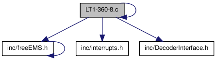
Go to the source code of this file.
Defines | |
| #define | LT1_360_8_C |
Functions | |
| void | LT1PTInit (void) |
| void | PrimaryRPMISR (void) |
| void | SecondaryRPMISR (void) |
| Use the rising and falling edges................... | |
| void | changeSyncStatus (unsigned char synced) |
| Change the accumulator mode to overflow every 5 inputs on PT0 making our 360 tooth wheel interrupt like a 72 tooth wheel. | |
Variables | |
| unsigned short | VCAS = 0 |
Detailed Description
LT1 Optispark.
Uses PT1 to interrupt on rising and falling events of the 8x cam sensor track. A certain number of 360x teeth will pass while PT1 is in a high or low state. Using that uniquek count we can set the positing of your Virtual CAS clock. After VCAS's position is set set PT7 to only interrupt on every 5th tooth, lowering the amount of interrupts generated, to a reasonable level.
- Note:
- Pseudo code that does not compile with zero warnings and errors MUST be commented out.
- Todo:
TODO This file contains SFA but Sean Keys is going to fill it up with
TODO wonderful goodness very soon ;-)
Definition in file LT1-360-8.c.
Define Documentation
| #define LT1_360_8_C |
Definition at line 48 of file LT1-360-8.c.
Function Documentation
| void changeSyncStatus | ( | unsigned char | synced | ) |
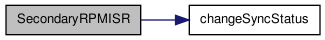
Change the accumulator mode to overflow every 5 inputs on PT0 making our 360 tooth wheel interrupt like a 72 tooth wheel.
PT0 Accumulator Mode
- Todo:
- TODO Decide if an explicit parameter is necessary if not use a existing status var instead for now it's explicit.
- Todo:
- TODO the register below does not exist and I couldn't figure out what you meant to do...
Definition at line 216 of file LT1-360-8.c.
References PACN0, PACTL, TCTL1, and TIOS.
Referenced by SecondaryRPMISR().
00216                                            {
00217     if (synced != 1) { /* disable accumulator counter, so an ISR is fired on all 360 teeth */
00218         PACTL = 0x00; /* disable PAEN and PBOIV */
00219         /*  (PACTL) 7   6    5     4     3    2    1    0
00220                       PAEN PAMOD PEDGE CLK1 CLK0 PAOVI PAI */
00221     }else{  /* enable accumulator so an ISR is only fired on every "5th tooth of the 360x track" */
00222 //      TIOS = TIOS &  "0xCC0x83" WTF!?LOL!! 0x80;  /* PT7 input */
00223 //      TCTL1 = TCTL1 &  "0xCC0x83" WTF!?LOL!! 0xC0; /* Disconnect IC/OC logic from PT7 */
00224         TIOS = TIOS & 0x80;  /* PT7 input */
00225         TCTL1 = TCTL1 & 0xC0; /* Disconnect IC/OC logic from PT7 */
00227         PACN0 = 0xFB ; /* Calculation, $00 – $05 = $FB. This will overflow in 5 more edges. */
00228         PACTL = 0x52; /* Enable PA in count mode, rising edge and interrupt on overflow  01010010 */
00229     }
00230 }
| void LT1PTInit | ( | void | ) |
Setup PT Capturing so that we can decode the LT1 pattern
- Todo:
- TODO Put this in the correct place
Definition at line 61 of file LT1-360-8.c.
| void PrimaryRPMISR | ( | void | ) |
Primary RPM ISR
- Todo:
- TODO Docs here!
- Todo:
- TODO possibly add code to make sure we are in divide mode, if not error out
- Todo:
- TODO fill in or remove the else
Definition at line 72 of file LT1-360-8.c.
References isSynced, PORTJ, PrimaryTeethDuringHigh, PrimaryTeethDuringLow, PTIT, TFLG, and VCAS.
00072                         {
00073     /* Clear the interrupt flag for this input compare channel */
00074     TFLG = 0x01;
00075
00076     /* Save all relevant available data here */
00077 //  unsigned short codeStartTimeStamp = TCNT;       /* Save the current timer count */
00078 //  unsigned short edgeTimeStamp = TC0;             /* Save the edge time stamp */
00079     unsigned char PTITCurrentState = PTIT;          /* Save the values on port T regardless of the state of DDRT */
00080 //  unsigned short PORTS_BACurrentState = PORTS_BA; /* Save ignition output state */
00081
00082 //  unsigned char risingEdge; /* in LT1s case risingEdge means signal is high */
00083 //  if(fixedConfigs1.coreSettingsA & PRIMARY_POLARITY){
00084 //      risingEdge = PTITCurrentState & 0x01;
00085 //  }else{
00086 //      risingEdge = !(PTITCurrentState & 0x01);
00087 //  }
00088
00089     PORTJ |= 0x80; /* Echo input condition on J7 */
00090     if(!isSynced){  /* If the CAS is not in sync get window counts so SecondaryRPMISR can set position */
00091         if (PTITCurrentState & 0x02){
00092             PrimaryTeethDuringHigh++;  /* if low resolution signal is high count number of pulses */
00093         }else{
00094             PrimaryTeethDuringLow++;  /* if low resolution signal is low count number of pulses */
00095         }
00096     }else{  /* The CAS is synced and we need to update our 360/5=72 tooth wheel */
00098         VCAS = VCAS + 10;  /* Check/correct for 10deg of CAM movement */
00100     }
00101 }
| void SecondaryRPMISR | ( | void | ) |
Use the rising and falling edges...................
Secondary RPM ISR
- Todo:
TODO Docs here!
TODO Add a check for 1 skip pulse of the 8x track, to prevent possible incorrect sync.
TODO Possibly make virtual CAS 16-bit so was can get rid of floating points and use for syncing
- Todo:
- TODO fill in or remove the else
Definition at line 110 of file LT1-360-8.c.
References changeSyncStatus(), fixedConfig1::coreSettingsA, Counters, Counter::crankSyncLosses, fixedConfigs1, isSynced, PORTJ, PRIMARY_POLARITY, PrimaryTeethDuringHigh, PrimaryTeethDuringLow, PTIT, TFLG, and VCAS.
00110                           {
00111     /* Clear the interrupt flag for this input compare channel */
00112     TFLG = 0x02;
00113
00114     /* Save all relevant available data here */
00115 //  unsigned short codeStartTimeStamp = TCNT;       /* Save the current timer count */
00116 //  unsigned short edgeTimeStamp = TC1;             /* Save the timestamp */
00117     unsigned char PTITCurrentState = PTIT;          /* Save the values on port T regardless of the state of DDRT */
00118 //  unsigned short PORTS_BACurrentState = PORTS_BA; /* Save ignition output state */
00119     unsigned char risingEdge;
00120     if(fixedConfigs1.coreSettingsA & PRIMARY_POLARITY){
00121             risingEdge = PTITCurrentState & 0x01;
00122         }else{
00123             risingEdge = !(PTITCurrentState & 0x01);
00124         }
00125     PORTJ |= 0x40;  /* echo input condition */
00126
00127     if (!isSynced & risingEdge){ /* If the CAS is not in sync get window counts and set virtual CAS position */
00128           /* if signal is high that means we can count the lows */
00129             switch (PrimaryTeethDuringLow){
00130             case 23: /* wheel is at 0 deg TDC #1, set our virtual CAS to tooth 0 of 720 */
00131             {
00132                 VCAS = 0 ;
00133                 changeSyncStatus((unsigned char) 1);
00134                 break;
00135             }
00136             case 38: /* wheel is at 90 deg TDC #4, set our virtual CAS to tooth 180 of 720 */
00137             {
00138                 VCAS = 180;
00139                 changeSyncStatus((unsigned char) 1);
00140                 break;
00141             }
00142             case 33: /* wheel is at 180 deg TDC #6 set our virtual CAS to tooth 360 of 720 */
00143             {
00144                 VCAS = 360;
00145                 changeSyncStatus((unsigned char) 1);
00146                 break;
00147             }
00148             case 28: /* wheel is at 270 deg TDC #7 set our virtual CAS to tooth 540 of 720 */
00149             {
00150                 VCAS = 540;
00151                 changeSyncStatus((unsigned char) 1);
00152                 break;
00153             }
00154             default :
00155             {
00156             Counters.crankSyncLosses++; /* use crankSyncLosses variable to store number of invalid count cases while attempting to sync*/
00157                 break;
00158             }
00159             PrimaryTeethDuringLow = 0; /* In any case reset counter */
00160             }
00161         }
00162     if(!isSynced & !risingEdge){/* if the signal is low that means we can count the highs */
00163             switch (PrimaryTeethDuringHigh){   /* will need to additional code to off-set the initialization of PACNT since they are not
00164                                                  evenly divisible by 5 */
00165             case 7: /* wheel is at 52 deg, 7 deg ATDC #8 set our virtual CAS to tooth 104 of 720 */
00166             {
00167
00168                 break;
00169             }
00170             case 12: /* wheel is at 147 deg, 12 deg ATDC #3 set our virtual CAS to tooth 294 of 720 */
00171             {
00172
00173                 break;
00174             }
00175             case 17: /* wheel is at 242 deg, 17 deg ATDC #5 set our virtual CAS to tooth 484 of 720 */
00176             {
00177
00178                 break;
00179             }
00180             case 22: /* wheel is at 337 deg, 22 deg ATDC #2 set our virtual CAS to tooth 674 of 720 */
00181             {
00182
00183                 break;
00184             }
00185             default :
00186             {
00187                 Counters.crankSyncLosses++; /* use crankSyncLosses variable to store number of invalid/default count cases while attempting to sync*/
00188                 break;
00189             }
00190
00191             }
00192             PrimaryTeethDuringHigh = 0;  /* In any case reset counter */
00193         }
00194     if(isSynced & risingEdge){  /* We are in sync and need to make sure our counts are good */
00195
00196         /* System is synced so use adjusted count numbers to check sync */
00198     }
00199 }
Variable Documentation
| unsigned short VCAS = 0 |
Definition at line 55 of file LT1-360-8.c.
Referenced by PrimaryRPMISR(), and SecondaryRPMISR().